Main Documents
Description
iMeter 5 Advanced Power Quality Monitor
Device Introduction
- iMeter 5 is one of CET’s latest Advanced Modular PQ Analyzer designed for the compliance monitoring market as it offers unsurpassed functionality by combining Class 0.2S Accuracy and advanced PQ Features in an industry-standard compact DIN96 form factor with a stunning, high resolution, color IPS LCD display and highly sensitive touch buttons. The iMeter 5 complies with such standards as IEC 62053-22: 2020 Class 0.2S, IEC 62052-31: 2015, IEC 61000-4-30 Ed. 3.1 Class S / Class A Compliant, IEC 61000-4-15, IEC 61000-4-7, EN 50160, IEEE Std 519-2022. Furthermore, the iMeter 5 offers up to 4GB memory, 4xDI, 2xDO, dual 10/100BaseT Daisy Chain Ethernet ports, an RS-485 port and an RJ45 port for modular I/O expansion. It can be easily integrated into Building Management Systems, Power Quality Monitoring Systems as well as Substation Automation Systems with Modbus TCP/RTU, BACnet/IP, SNMP, IEC 61850, IEC 60870-5-104 and other protocols. These features make the iMeter 5 a vital component of various systems for different applications.
Product Highlight
- Low-Cost Three-Phase Multifunction Meter
- IEC62053-22 Class 0.5S
- DIN96 (92x92mm Cutout)
- Backlit Dot-Matrix LCD Display
- Harmonics, Demands & TOU, Energy Log, Max/Min Log and Event Log
- Waveform Capture on Screen
- Modbus RTU, BACnet MSTP, Metasys N2 or DNP
- 1xRS-485 + 2nd RS-485(Optional)
- Optional 4xDI, 2xRO/DO, Optional I4, RTD
Typical Application
- Industrial, Commercial and Utility Substation Metering
- Building, Factory and Process Automation
- Sub-metering and Cost Allocation
- Energy Management and Power Quality Monitoring
Related Products
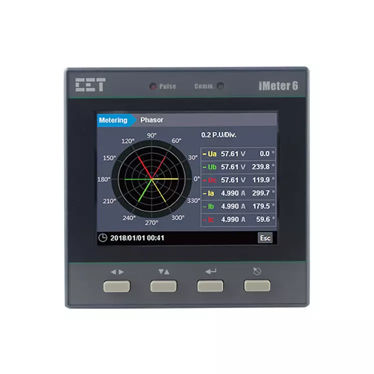
iMeter 6 Advanced Power Quality Monitor
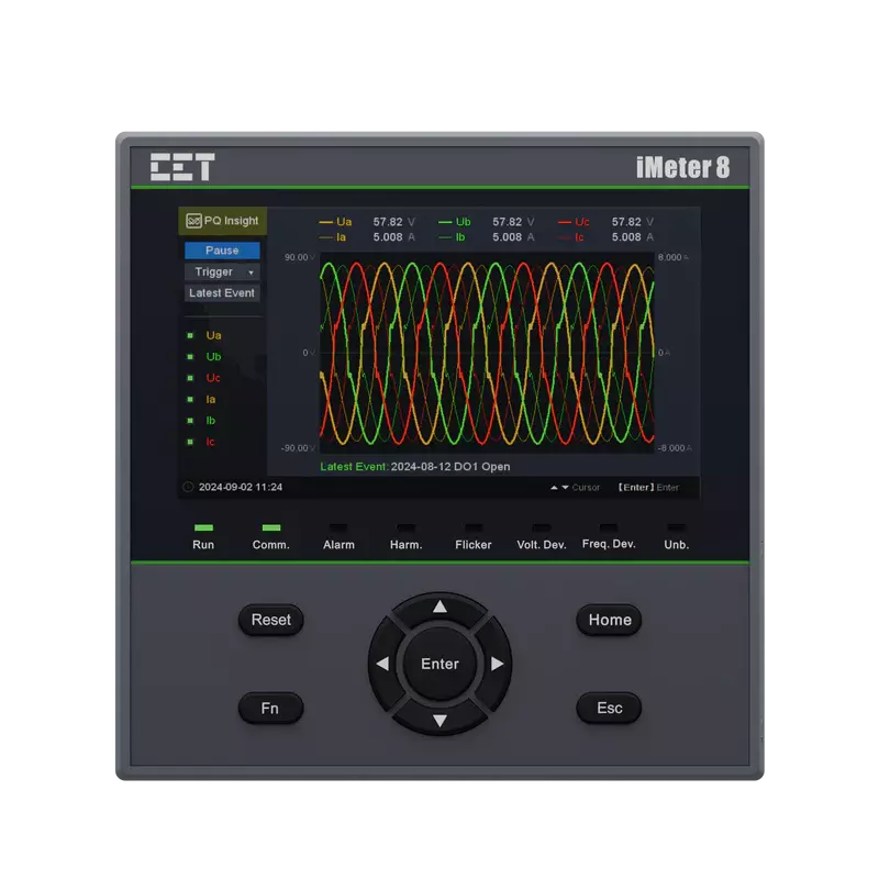
iMeter 8 Advanced Power Quality Monitor

iMeter 7A Advanced Power Quality Monitor
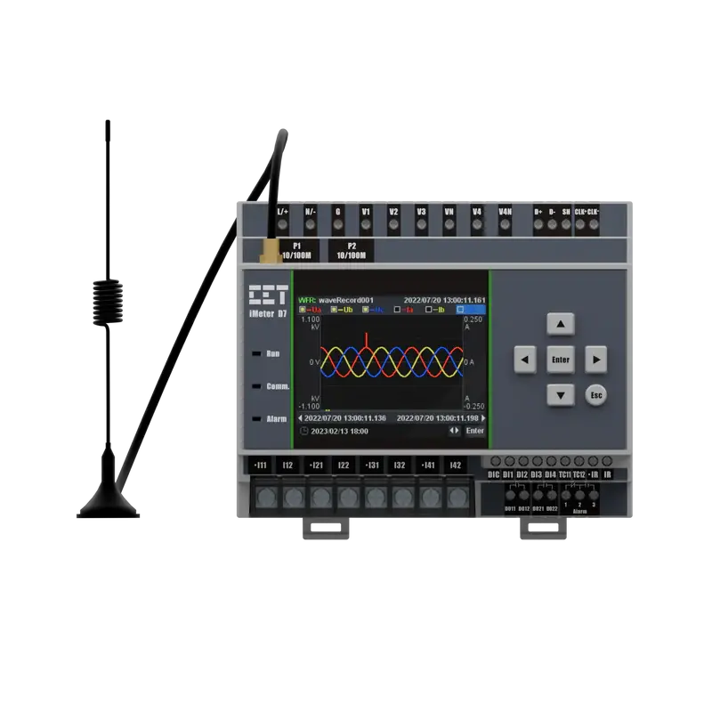
iMeter D7 Advanced Power Quality Monitor
Specification
Technical Specification
Voltage Inputs(V1,V2,V3,VN) | |
|---|---|
| Standard Un | 400ULN/690ULL |
| Range | 10V to 1.2Un |
| Overload | 1.2xUn continuous, 2xUn for 1 s |
| Burden | <0.02VA/phase |
| Measurement Category | CAT III up to 600ULL |
| Frequency | 45-65Hz |
Current Inputs(I11,I12,I21,I22,I31,I32) | |
| Standard In | 5A(Optional 1A) |
| Range | 0.1% to 200%In |
| Starting Current | 0.1%In |
| Overload | 2xIn continuous, 20xIn for 1 s |
| Measurement Category | CAT III up to 600ULL |
| Burden | <0.15VA per phase@5A |
Optional I4 Input(I41,I42) | |
| In | 5A(5A/1A Auto-Scale) |
| Range | 0.1% to 200% In |
| Starting Current | 0.1% In |
Power Supply(L+,N-) | |
| Standard | 95-250VAC/DC,±10%,47-440Hz |
| Optional | 20-60VDC |
| Burden | <2W |
| Overvoltage Category | CAT III up to 300VLN |
Digital Inputs(DI1,DI2,DI3,DI4,DIC) | |
| Type | Dry contact,24VDC internally wetted |
| Sampling | 1000Hz |
| Hysteresis | 1ms minimum |
Digital Outputs(DO11,DO12,DO21,DO22) | |
| Type | Form A Mechanical Relay |
| Loading | 5A@250VAC or 30VDC |
| Load Type | Resistive |
Pulse Outputs(E1+,E1-,E2+,E2-) | |
| Type | Form A Solid State Relay |
| Isolation | Optical |
| Load Type | Resistive |
| Output | Optocoupler output as ON-OFF |
| Max.Load Voltage | 50VDC |
| Max.Forward Current | 50mA |
Installation Torque | |
| Current Inputs | 12 Ib-in(1.3N.m) |
| Power Supply,Voltage Inputs,RS-485 and I/O | 5 Ib-in(0.5N.m) |
Environmental Conditions | |
| Operating Temp. | -25 °C to + 70°C |
| Storage Temp. | -40 °C to + 85°C |
| Humidity | 5% to 95% non-condensing |
| Atmospheric Pressure | 70 kPa to 106 kPa |
| Altitude | <2000m |
| Location/Mounting | For indoor use only |
Mechanical Characteristics | |
| Panel Cutout | 92x92mm(3.62”x3.62”) |
| Unit Dimensions | 96x96x88mm |
| IP Rating | IP65 |
Communications | |
| Protocol | Modbus RTU, BACnet MS/TP, Metasys N2 and DNP3.0 |
| RS-485 Port | 1+(1 Opt.) |
Features Summary | |
| Display (Backlit) | Dot-Matrix LCD (Backlit) |
| Type of Measurement | ULN per Phase &Avg. ULL per Phase&Avg. Current per Phase &Avg. Neutral Current (Meas./Calc.) Frequency kW per Phase & Total kvar per Phase & Total kVA per Phase& Total PF per Phase& Total kWh lmport/Export kvarh Import/Export kVAh Total |
| Power Quality | THD Voltage & Current TOHD Voltage & Current TEHD Voltage & Current 2nd-31st Harmonics K-Factor Voltage/Current Unbalance |
| Battery-backed Real-time Clock | √ |
| Demands | Present , Predicted Demands and Max.Demands for This Month & Last Month |
| Multi-Tariff TOU capability | Two TOU schedules, each providing: 12 Seasons 90 Holidays 20 Daily Profiles, each with 12 Periods in 15-minute interval 8 Tariffs |
| Diagnostics | √ |
| Setpoints | 9 Setpoints |
Logs | |
| Max./Min.Log | This month & Last Month |
| Freeze Logs(Optional) | 60 Daily Freeze Logs, 36 Monthly Freeze Logs |
| Data Recorder(Optional) | 5 Data Recorders Max. Recording Depth @ 10000 records |
| SOE Log | 100 entries |
| On-board Log Memory | (4MB Opt.) |
Accuracy
| Parameters | Accuracy | Resolution |
|---|---|---|
| Voltage | ±0.2% | 0.001V |
| Current | ±0.2% | 0.001A |
| I4(measurement) | ±0.2% | 0.001A |
| P,Q,S | ±0.5% | 0.001kx |
| kWh,kVAh | IEC 62053-22 Class 0.5S ANSI C12.20 Class 0.2 EN 50470-1/3:2006 Class C | 0.1kXh |
| kvarh | IEC 62053-24 Class 0.5S IEC 62053-23 Class 2 | 0.1kvarh |
| PF | ±0.5% | 0.001 |
| Frequency | ±0.02Hz | 0.01Hz |
| THD | IEC 61000-4-7 Class B | 0.001% |
| K-Factor | IEC 61000-4-7 Class B | 0.001 |
| Phase Angle | ±1° | 0.1° |
Standards of Compliance
Safety Requirements | |
|---|---|
| CE LVD 2014/35/EU | EN 61010-1: 2010 EN 61010-2-030: 2010 |
| Electrical Safety in Low Voltage Distribution Systems up to 1000Vac and 1500Vdc | IEC 61557-12:2018(PMD) |
| Insulation AC Voltage: 2kV@1 minute Insulation Resistance: >100MΩ Impulse Voltage: 6kV,1.2/50µs | IEC 62052-31:2015 |
Electromagnetic Compatibility CE EMC Directive 2014/30/EU(EN 61326:2013) | |
Immunity Tests | |
| Electrostatic Discharge | EN 61000-4-2:2009 |
| Radiated Fields | EN 61000-4-3:2006+A1:2008+A2:2010 |
| Fast Transients | EN 61000-4-4:2012 |
| Surges | EN 61000-4-5:2014+A1:2017 |
| Conducted Disturbances | EN 61000-4-6:2014 |
| Magnetic Fields | EN 61000-4-8:2010 |
| Voltage Dips and Interruptions | EN 61000-4-11:2004+A1:2017 |
| Ring Waves | EN 61000-4-12:2017 |
Emission Tests | |
| Limits and Methods of Measurement of Electromagnetic Disturbance Characteristics of Industrial,Scientific and Medical(ISM) Radio-Frequency Equipment | EN 55011:2016 |
| Limits and Methods of measurement of Radio Disturbance Characteristics of Information Technology Equipment | EN 55032:2015 |
| Limits for Harmonic Current Emissions for Equipment with Rated Current≤16A | EN 61000-3-2:2014 |
| Limitation of Voltage Fluctuations and Flicker in Low-Voltage Supply Systems for Equipment with Rated Current≤16A | EN 61000-3-3:2013 |
| Emission Standard for Residential, Commercial and Light-Industrial Environments | EN 61000-6-4:2007+A1:2011 |
RED (Radio Equipment Directive) | |
| Assessment of Electronic and Electrical Equipment Related to Human Exposure Restrictions for Electromagnetic Fields (0Hz - 300 GHz) | EN/IEC 62311: 2020 |
| Short Range Devices (SRD) Operating in the Frequency Range 25 MHz to 1000MHz | ETSI EN 300 220-1V3.1.1: 2017 ETSI EN 300 220-2 V3.1.1: 2017 |
| Audio/Video, Information and Communication Technology Equipment -Part 1: Safety Requirements | IEC 62368-1: 2018 |
Mechanical Tests | |
| Spring Hammer Test | IEC 62052-11:2003 |
| Vibration Test | IEC 62052-11:2003 |
| Shock Test | IEC 62052-11:2003 |
Wiring Mode
Wiring Mode | |
|---|---|
| 3P4W | 3-Phase 4-Wire Wye Direct Connection with 3CTs 3-Phase 4-Wire Wye Direct Connection with 4CTs 3-Phase 4-Wire Wye with 3PTs and 3CTs 3-Phase 4-Wire Wye with 3PTs and 4CTs |
| 3P3W | 3-Phase 3-Wire Direct Delta Connection With 3CTs 3-Phase 3-Wire Direct Delta Connection with 2CTs 3-Phase 3-Wire Delta with 2PTs and 3CTs 3-Phase 3-Wire Delta with 2PTs and 2CTs |
| 1P3W | 1-Phase 3-Wire Direct Connection with 2CTs |
| 1P2W L-N | 1-Phase 2-Wire, Uln Direct Connection with 1CT |
| 1P2W L-L | 1-Phase 2-Wire, Ull Direct Connection with 1CT |